
Hvac Drawing
Hvac Drawing - For heating systems, the diagram might include the evaporator coil, blower. Here you will find the hvac equipment such as air conditioners, air handlers, fan coil units, fans, chillers, cooling towers, pumps, air distribution, expansion tanks, boilers, vfd’s (variable frequency drives), condensers and various other components. Each type of drawing contains one aspect of the hvac system. Create diagrams of heating and air conditioning systems, air flows, electrical systems, ducts, and piping for both home and commercial properties. Web generally, there are 4 types of hvac drawings which are the hvac layout drawing, hvac schematic drawing, installation details for hvac and single line diagram for hvac panels.
So, identify the btu needed for each room and divide it by 30 to get the required cfm for the respective room. Drawing courtesy pae consulting engineers. Web an hvac diagram is used to illustrate all of the different components of a residential heating and cooling system. Web an hvac floor plan is a detailed drawing, often created by a specialized engineer, showing the placement of all the key hvac components in relation to the building’s structure, including walls, windows, doors, and stairs. Then, understand the meaning of the symbols used in hvac drawings. To read hvac duct drawings, start by identifying the hvac equipment location and details. Create diagrams of heating and air conditioning systems, air flows, electrical systems, ducts, and piping for both home and commercial properties.

HVAC layout 2d cad drawing of autocad file Cadbull
Thanks to recent developments in ai, the potential for an even more robust form generative design has heightened significantly. Drawing courtesy pae consulting engineers. It will still be some. Each type of drawing contains one aspect of the hvac system. Web hvac drafting is a crucial aspect of the hvac (heating, ventilation, and air conditioning).
Hvac Drawing at GetDrawings Free download
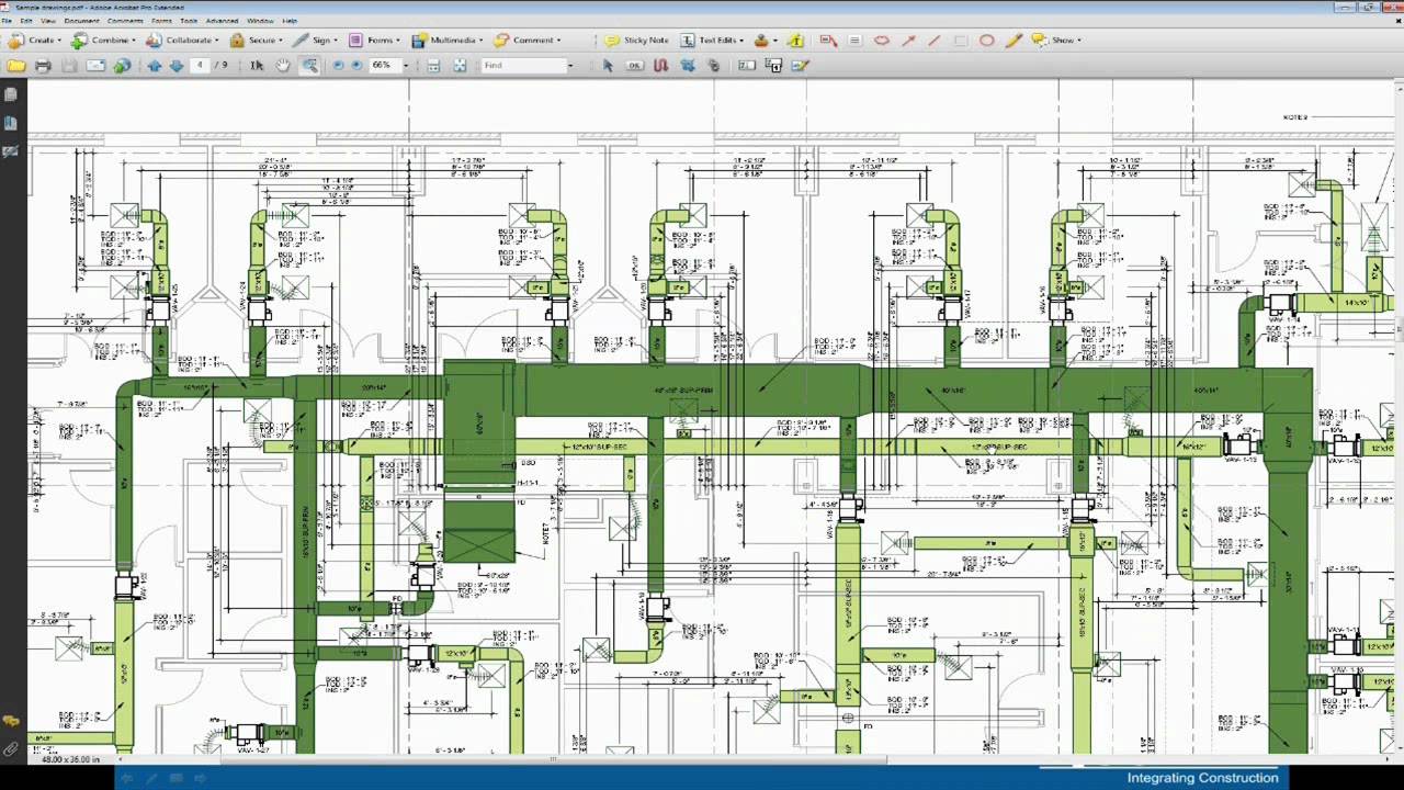
Web like any other floor plan or architectural plan, an hvac plan refers to the 2d or 3d representation of all the materials or equipment needed by a special engineer to create, set up, and maintain the heating and cooling system of any other building. Web duct drawings are hvac drawings that shows the layout.
Hvac Drawing at GetDrawings Free download
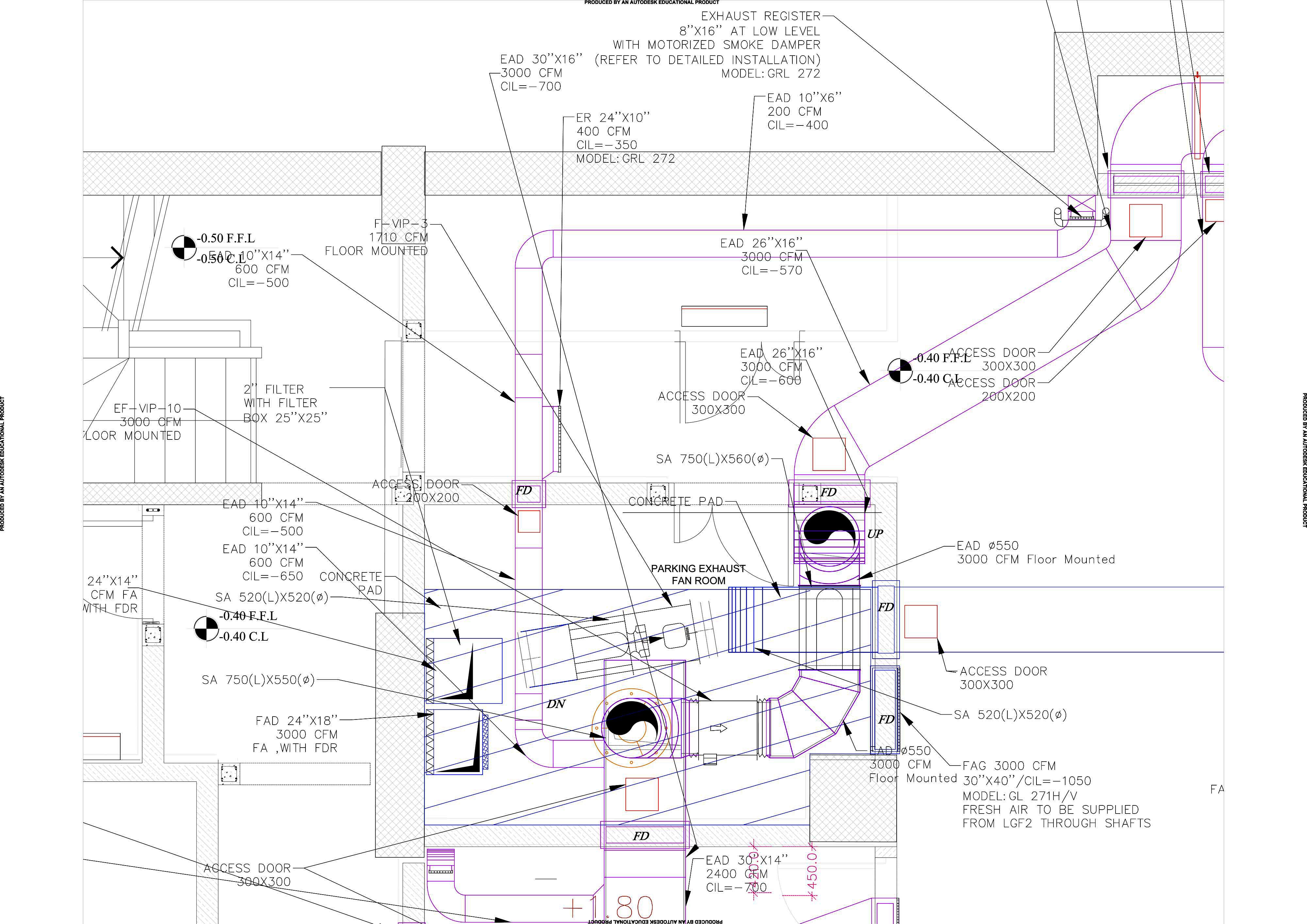
Next, identify whether the hvac drawing is a layout, section, elevation or schematic drawing. Web ventilation system drawing from slab & wall openings to grilles & dampers, a ventilation drawing plays a vital role in designing the hvac system. Web hvac drafting is a crucial aspect of the hvac (heating, ventilation, and air conditioning) industry,.

AutoCAD Tutorial HVAC Drawing Villa In Dubai AutoCAD HVAC How to
Web an hvac floor plan is a detailed drawing, often created by a specialized engineer, showing the placement of all the key hvac components in relation to the building’s structure, including walls, windows, doors, and stairs. Web hvac drawing templates diagram categories agile workflow aws diagram brainstorming cause and effect charts and gauges decision tree.

HVAC Plans by Raymond Alberga at Hvac system design
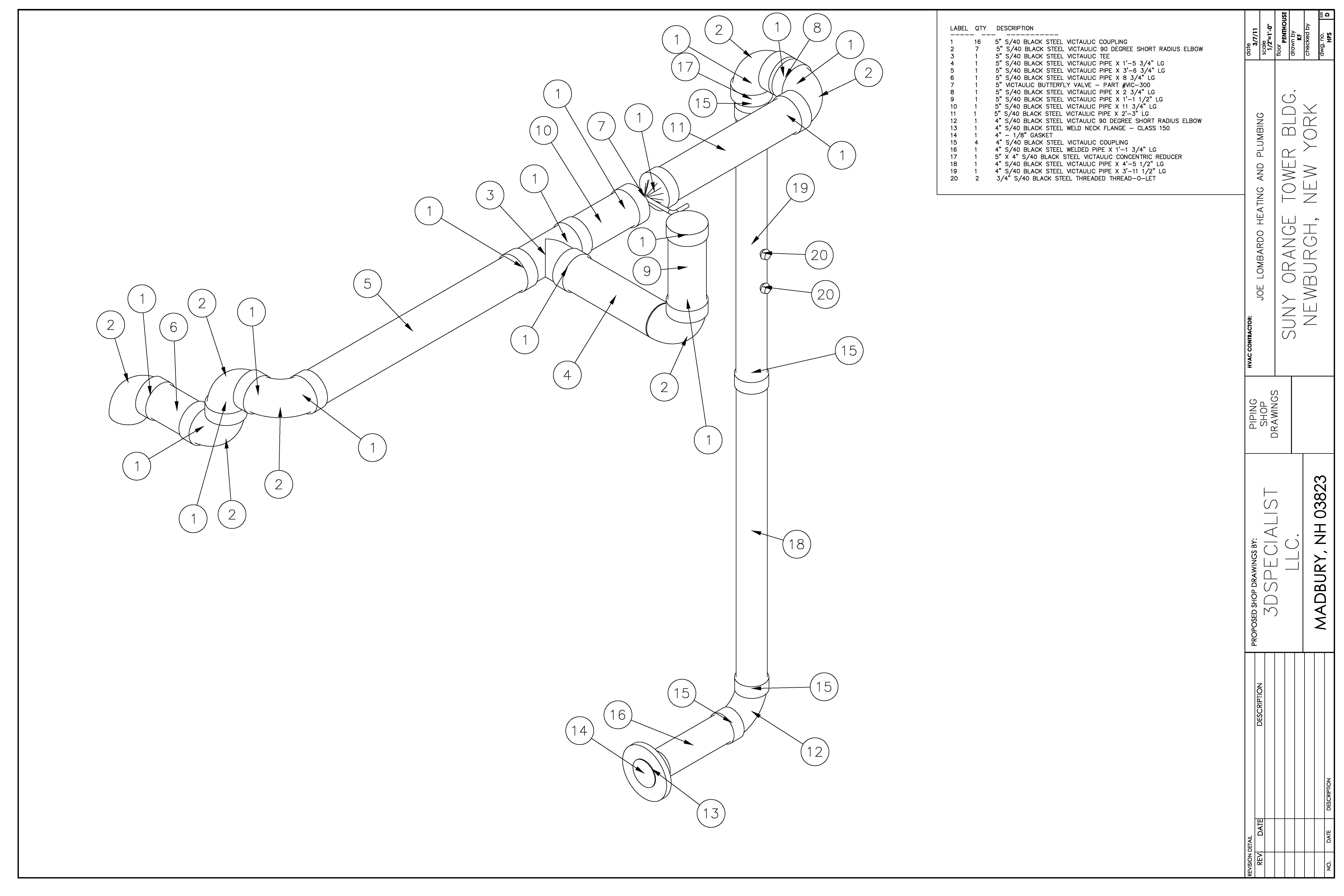
These drawings serve as a blueprint for hvac installers, engineers, and contractors, guiding them in the installation, repair, and maintenance of heating and cooling systems. So, identify the btu needed for each room and divide it by 30 to get the required cfm for the respective room. Hvac shop drawings are especially created for installation.
Hvac Drawing at GetDrawings Free download
Web like any other floor plan or architectural plan, an hvac plan refers to the 2d or 3d representation of all the materials or equipment needed by a special engineer to create, set up, and maintain the heating and cooling system of any other building. Web an hvac diagram is used to illustrate all of.

A complete guide to HVAC drawings and blueprints
Web like any other floor plan or architectural plan, an hvac plan refers to the 2d or 3d representation of all the materials or equipment needed by a special engineer to create, set up, and maintain the heating and cooling system of any other building. Schedules help to find the details of the equipment or.
Hvac Drawing at GetDrawings Free download
Web an hvac diagram is used to illustrate all of the different components of a residential heating and cooling system. Web an hvac floor plan is a detailed drawing, often created by a specialized engineer, showing the placement of all the key hvac components in relation to the building’s structure, including walls, windows, doors, and.
Hvac Drawing at GetDrawings Free download
Drawing courtesy pae consulting engineers. Demystified hvac systems are indeed the unsung heroes when it comes to comfortable buildings, silently regulating temperature, air quality, along with circulation. The system may consist of a central unit or separate units for heating and cooling, air filters for improved air quality, and ventilation systems to circulate fresh air.

Commercial HVAC Installation in Denver, CO by CMI Mechanical
Web like any other floor plan or architectural plan, an hvac plan refers to the 2d or 3d representation of all the materials or equipment needed by a special engineer to create, set up, and maintain the heating and cooling system of any other building. So, identify the btu needed for each room and divide.
Hvac Drawing General notes, abbreviations, legends, and symbols, are found on the first page of the mechanical drawings. They provide crucial information to various stakeholders including: These vary from one engineer to the next, but there are some similarities that will help you figure the differences out. Demystified hvac systems are indeed the unsung heroes when it comes to comfortable buildings, silently regulating temperature, air quality, along with circulation. Then, understand the meaning of the symbols used in hvac drawings.
These Drawings Serve As A Blueprint For Hvac Installers, Engineers, And Contractors, Guiding Them In The Installation, Repair, And Maintenance Of Heating And Cooling Systems.
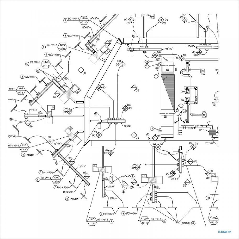
Web hvac drawing templates diagram categories agile workflow aws diagram brainstorming cause and effect charts and gauges decision tree education emergency planning engineering block diagram circuit diagram electrical plan hvac drawing logic diagram piping diagram power plant diagram process flow diagram welding diagram. Next, identify whether the hvac drawing is a layout, section, elevation or schematic drawing. The design of the hvac plan may vary depending on the size. Web within hvac drawings, schematic drawings, plan drawings, elevation drawings, and isometric drawings serve as technical representations or illustrations to convey the design and layout of hvac systems.
The System May Consist Of A Central Unit Or Separate Units For Heating And Cooling, Air Filters For Improved Air Quality, And Ventilation Systems To Circulate Fresh Air Throughout The Home.
Web the hvac equipment is shown on the mechanical equipment schedule drawings. Hvac shop drawings are especially created for installation and fabrication of mep components. So, how do you read hvac duct drawings? This equipment needs to be described as it is used to estimate, order, and install at the site.
Web Ventilation System Drawing From Slab & Wall Openings To Grilles & Dampers, A Ventilation Drawing Plays A Vital Role In Designing The Hvac System.
Thanks to recent developments in ai, the potential for an even more robust form generative design has heightened significantly. Web generally, there are 4 types of hvac drawings which are the hvac layout drawing, hvac schematic drawing, installation details for hvac and single line diagram for hvac panels. Calculate the cfm for each room most hvac units are designed to have a 400 cfm of airflow for every 12000 btu or 1 ton of cooling capacity and 12000 btu divided by 400 cfm is 30. However, behind the scenes is a complex network of components teamed with ductwork, precisely mapped out in a specific language:
Web Hvac Drawings Serve As The Roadmap For Installing And Maintaining Hvac Systems.
The hvac drawings include equipment and diffusers, which are provided in symbols on the drawings. Create diagrams of heating and air conditioning systems, air flows, electrical systems, ducts, and piping for both home and commercial properties. Web heating, ventilating, and air conditioning (hvac) default recent 391 cad drawings for category: To read hvac drawings, start by understanding the drawing title block.